01 / DILUTION
Less oxygen concentration
A measured quantity of exhaust displaces fresh intake air. It is not there to make power; it changes the chemistry and temperature of combustion.


Common issues / EGR calibration
An EGR delete changes an air-path system that also talks to fuelling, boost, diagnostics, thermal control and—on many diesels—DPF regeneration. A five-minute flash can hide a warning lamp. Only a coordinated calibration and measured verification can show what the engine is actually doing.
Road-use note: an EGR valve is manufacturer-fitted emissions equipment. If it is missing, obviously modified or obviously defective, the current DVSA MOT manual lists that as a major defect. For a road vehicle, diagnosis, cleaning, repair or replacement is the compliant route.
Closing a valve is one command. Keeping the whole control system coherent is the job.
Air model + actuator control + diagnostics + fuelling + boost + thermal strategy + DPF regenerationStart with what the system is for
That sounds counter-intuitive until the target is clear: reduce peak combustion temperature and therefore reduce formation of nitrogen oxides (NOx) in the operating areas where the manufacturer commands EGR.
01 / DILUTION
A measured quantity of exhaust displaces fresh intake air. It is not there to make power; it changes the chemistry and temperature of combustion.
02 / TEMPERATURE
Recirculated gas absorbs heat and slows the combustion process. Less time at very high temperature means less thermal NOx formation.
03 / TRADE-OFF
EGR rate, boost, injection timing, swirl and fuelling are calibrated together. Moving one part changes the conditions assumed by the others.
Why valves go wrong
Deposits reduce the effective opening and load the actuator. Thermal cycling, cooler faults, vacuum leaks, worn linkages and electrical feedback faults add their own failure modes.
Deposits or a failed actuator stop the valve reaching its commanded opening. Fresh-air mass stays higher than the ECU expects.
The valve cannot seat, reacts slowly or opens when it should not. Idle quality, smoke, response and boost control can suffer.
An electric actuator may report slow movement, a control deviation or a position range fault even if the valve eventually moves.
Split vacuum hose, failed pressure converter, wiring, a biased MAF/MAP sensor or restricted pipework can all make EGR flow wrong.
Coolant leakage, deposits or incorrect bypass operation can expose intake components to a thermal condition they were not designed to sustain.
Stuck open under boost
If the valve should be shut at load but remains open, the engine may lose a large amount of effective fresh-air charge and manifold pressure. Depending on the pressure difference at that operating point, exhaust can be forced into the intake or boosted charge can escape back towards the exhaust side. Either direction corrupts the air model and can produce underboost, smoke and severe power loss.
It can also be hard on the turbo. If the ECU sees boost below target, it may command more VGT closure or wastegate duty and drive the compressor harder. A substantial leak can therefore make the turbo spin much faster than expected while the manifold still fails to reach target. Turbocharger technical guidance identifies leaks between the compressor and engine as a recognised cause of overspeed because the turbo must work harder to deliver the requested air.
Pressure direction is not universal: it changes with engine speed, load, VGT position and exhaust-manifold-to-intake pressure ratio. The correct diagnosis compares commanded and actual boost, MAF, EGR position, exhaust pressure where available and turbo control duty—not just the presence of an EGR code.
Why an EGR fault can look like a MAF fault
On many diesel systems the MAF is part of the EGR feedback loop. The ECU knows the fresh-air mass it expects when exhaust gas is being admitted. If actual fresh air is too high or too low, the flow calculation fails its plausibility check.
Expected exhaust never arrives, so the engine draws more fresh air through the MAF. The ECU may log insufficient EGR flow or an air-mass plausibility/range fault.
Unexpected exhaust displaces fresh air. The ECU may detect excessive flow; the engine can idle poorly, hesitate or produce smoke because the available oxygen is not what the fuelling model expected.
Vacuum vs electronic EGR
Vehicle designs vary, but the basic diagnostic split is useful: older pneumatic systems often infer flow indirectly; modern electric valves are more likely to report position or actuator behaviour as well.
Important: a position sensor proves where the actuator believes the valve is. It does not prove that the gas passage is clear, the cooler is healthy or the actual EGR mass flow is correct.
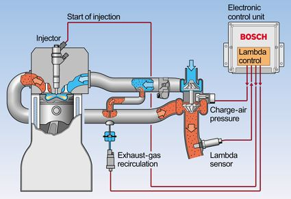
Inside a Bosch-style diesel strategy
A simplified calibration view starts with an operating-point target—often EGR rate or fresh-air mass against engine speed and injected quantity/load. That target then passes through temperature, pressure, transient and operating-mode corrections before closed-loop control moves the valve.
A correct calibration is strategy-specific. It must preserve the operating modes, safety functions and aftertreatment behaviour the vehicle still needs. This diagram explains the control problem; it is deliberately not a how-to for defeating emissions equipment.
EGR hysteresis, explained
On many older Bosch EDC16 applications, speed-dependent upper and lower injected-quantity curves form part of the EGR monitoring and shut-off logic. Tuners commonly call these the EGR hysteresis maps.
Hysteresis means the switch-off point and switch-on point are deliberately different. The gap between them prevents the system changing state repeatedly when load sits close to one boundary.
In the supplied calibration example, engine speed is the axis and the curve value is injected fuel mass, shown in mg/hub—milligrams per combustion stroke. The upper curve is generally above the lower curve.
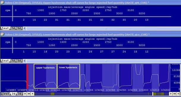
If the injected quantity hovered around a single boundary, tiny load changes could repeatedly enable and disable EGR. Separate upper and lower limits create a deadband and preserve the last valid state.
On many EDC16 variants, changing the relevant hysteresis condition can keep the normal EGR controller in a shut-down state. It is one of the most common older-Bosch approaches. Other software uses different maps, switches, target-air-mass logic or multiple high- and low-pressure EGR paths.
Normal running, warm-up, protection and DPF regeneration may not use the same branch. Some documented EDC16 families contain dedicated EGR/throttle control values for regeneration. Editing every similar-looking hysteresis pair can therefore alter the regeneration air path or stop a regeneration condition being satisfied.
The risk is collateral damage to shared air-control or regeneration-mode logic. A correct strategy identifies which pair belongs to normal EGR control, which pairs belong to other modes, and then proves requested and completed regeneration in live data. Similar shape and proximity in a binary file are not proof of function.
EGR delete with the DPF retained
An active regeneration is a coordinated thermal event, not one extra injection. The ECU uses a soot model and/or differential pressure, checks enabling conditions, then coordinates air path, boost, injection and temperature to oxidise soot in the filter.
Calculated soot and differential pressure indicate filter loading.
Temperature, fuel level, active faults and operating state must allow regeneration.
Injection, throttle, turbo and EGR strategy are coordinated to raise DOC/DPF temperature.
EGT sensors and the soot model keep the event effective and within thermal limits.
Pressure and model values should show that restriction and soot mass have fallen.
Depending on the ECU and vehicle, EGR can be commanded closed in the relevant modes while the remaining air-path model, temperature management, diagnostic permissions and regeneration state machine stay coherent. It must be demonstrated in data, not assumed from the absence of a lamp.
Broad DTC suppression, the wrong switch/patch, implausible airflow, an unhandled mode transition or changed soot-model inputs can prevent a requested regeneration, end it early or make the ECU misjudge filter loading.
No—not automatically. Less EGR usually means more oxygen is available, and research shows EGR rate has a complex, operating-point-dependent effect on soot formation and oxidation. But a poor file can still increase particulate loading through uncoordinated fuelling, smoke limitation, boost or combustion timing. Failed or incomplete regenerations will then make filter loading rise regardless of what happened to engine-out soot.
Software-off vs physically sealed
The key word is genuinely. A zero request in one map or a dashboard with no warning lamp does not prove the valve stays closed through warm-up, overrun, regeneration, protection states and every fallback mode.
If commanded and actual position agree, the seat seals and logged airflow confirms no unintended recirculation, an additional plate may add nothing mechanically.
If the actuator remains plugged in, incomplete software may still command slight or partial opening. A slow or contaminated valve may also fail to return fully to its seat.
A plate can mask the flow symptom without repairing a failed cooler, actuator, pipe or control system. The underlying hardware still needs inspection.
Temperature is not one number
Because EGR changes oxygen concentration, heat capacity and combustion timing, removing it can raise peak in-cylinder temperature and NOx in the regions where EGR was active. Exhaust temperature is not guaranteed to rise or fall: it also depends on injection timing, fuel quantity, boost, lambda and aftertreatment mode.
Especially where the original calibration relied on dilution to control NOx and combustion rate.
Timing, excess air, turbo work and post-injection can outweigh the EGR change itself.
Too cool will not oxidise soot effectively; too hot with a heavily loaded filter can damage the substrate.
The anonymous-file chain
Tool ownership is not calibration knowledge. When responsibility is passed through portals, resellers and automated patch services, the local installer may not know which strategy changed, what was suppressed or whether that exact software version was validated with its DPF retained.
Our strongest recommendation: do not hand this work to a roadside agent or general garage that depends entirely on an unknown file supplier. Ask who changed the strategy, what was changed, whether the exact ECU software was tested with the DPF retained, and which live data will prove the result. If the installer cannot answer, the low price is not worth the long-term uncertainty.
Fault-code families
Generic code descriptions are a starting point. Manufacturer-specific subcodes and live data usually carry the useful detail.
General flow/control fault.
Often restriction, no vacuum, stuck shut or high fresh-air mass.
Valve not seating, unexpected opening or low fresh-air mass.
Wiring, solenoid, actuator or ECU-side electrical issue.
Commanded movement and feedback do not agree.
Low, high, intermittent or circuit-range faults depend on system design.
The MAF may be correct while EGR flow is not.
Investigate why loading rose or regeneration did not complete.
What competent work looks like
For road vehicles, the first decision is whether the EGR should be cleaned, repaired or replaced. Where a non-road application legitimately requires a different calibration, the same engineering discipline still applies.
Codes, freeze-frame, actuator test, vacuum, wiring, MAF/MAP response, cooler and pipework.
Confirm valve seating, deposits, manifold condition, leaks, DPF pressure and sensor health.
Match the exact ECU, software version, actuator type and aftertreatment configuration.
Air targets, monitoring, fuelling, boost, torque, thermal protection and regen modes must agree.
Check position, MAF/MAP, lambda where available, boost, EGT, DPF state and completed regeneration behaviour.
Technical basis
Primary and workshop-technical sources were used for the underlying system behaviour. Application-specific diagnosis must still follow the manufacturer information for the vehicle in front of us.
Straight answers
It is the deliberate gap between the condition that switches EGR control off and the condition that allows it to switch back on. On many Bosch EDC16 applications the limits are speed-dependent injected-quantity curves. The gap prevents rapid on/off cycling when engine load sits close to the boundary.
Technically, some ECU strategies can be calibrated so the DPF continues to load-model and regenerate correctly. It is not universal, it must be strategy-specific and it must be verified. For a public-road vehicle, modifying manufacturer-fitted emissions equipment creates compliance and MOT problems, so diagnosis and repair are the appropriate route.
No. If the valve is truly closed, seals correctly and logged airflow proves there is no unintended flow, a plate may add nothing. A plate must never be used as a substitute for diagnosing a cooler, valve, actuator or manifold fault.
Because the sensor may have been accurately reporting an airflow mismatch caused by the EGR system. Compare commanded EGR, valve feedback, MAF response, MAP/boost, vacuum supply and intake leaks before condemning another sensor.
No. The file may simply suppress the relevant DTC. Regeneration status, soot loading, differential pressure, airflow plausibility, valve behaviour and temperatures need to be checked in live data over the operating modes that matter.
No. Temperature and fuel consumption depend on the complete combustion and aftertreatment strategy. Removing dilution changes combustion, but injection timing, boost, lambda, torque demand and regeneration frequency decide the real result.
Do not buy another guess
Tell us the model, engine, current fault codes, previous software work and whether the DPF is still fitted. We will explain the sensible diagnostic route before recommending work.